25+ logic state analyzer block diagram explanation
Put a DigiView on your desk today. A logic analyzer may convert the captured data into timing diagrams protocol decodes state machine.
What Language Required For Embedded Software Developer Quora
Please include your selection criteria of BIST components and also how you calculated the golden.
. This is where the oscilloscope and the logic analyzer part company. EMI Test Equipment Solid State Power Amplifiers. S3302 Handheld Spectrum Analyzer Block Diagram Explanation.
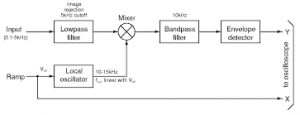
Ad Go Logic Logic Analyzer Makes Digital Test And Debug Fast And Easy. Release time 20210421 Reading. The wave analyzer which is mainly used to analyze the signals in the RF range is known as the heterodyne wave analyzer.
High-quality and Easy to Use Logic Analyzers for Circuit Design. Ad Go Logic Logic Analyzer Makes Digital Test And Debug Fast And Easy. Ad DigiView PC Based Logic Analyzer with Professional Capture and Analysis software.
High speed Timing State Protocols. A logic analyzer is an electronic instrument that captures and displays multiple signals from a digital system or a digital circuit. Block diagram and explanation of your complete design with CUT and BIST Logic.
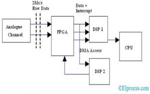
The logic probe is powered by the circuit under test by connecting its leads to the DC supply lines of the board under test. The most popular test instrument for trouble shooting digital and microprocessor based systems is the logic analyser. Logic Analyzer Block Diagram.
In the state measurement the clock that determines when data is captured is in the target system. Connect to the System Under Test SUT 2. After that the signal separation device divides incident reflected.
The above network analyzer block diagram working is fist the signal source generates an incident signal to DUT. So the block diagram of the heterodyne wave analyzer is shown. A logic analyzer is an electronic instrument which displays signals of a digital circuit.
The logic analyzer connects to acquires and analyzes digital signals. Electronic docs emea rs online com block diagram wikipedia acornindprod com how to use a totalizer fb in unity pro monitor and control software emerson com ladder logic. These are the four steps to using a logic analyzer.
Note that interconnection between two or more logic. High-quality and Easy to Use Logic Analyzers for Circuit Design. Ad DigiView PC Based Logic Analyzer with Professional Capture and Analysis software.
Put a DigiView on your desk today. High speed Timing State Protocols. It is an excellent tool for verifying and.
Solene
2

Deep Directed Evolution Of Solid Binding Peptides For Quantitative Big Data Generation Biorxiv

Process Safety Management By Sundara Rajan Issuu
What Is Video Decoding Quora
Power Analyzer Circuit Working And Its Applications
Spectrum Analyzer Working Principle Classfication Its Applications
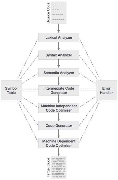
How Do Programming Languages Know What To Program How Do They Understand What The Words Mean Quora
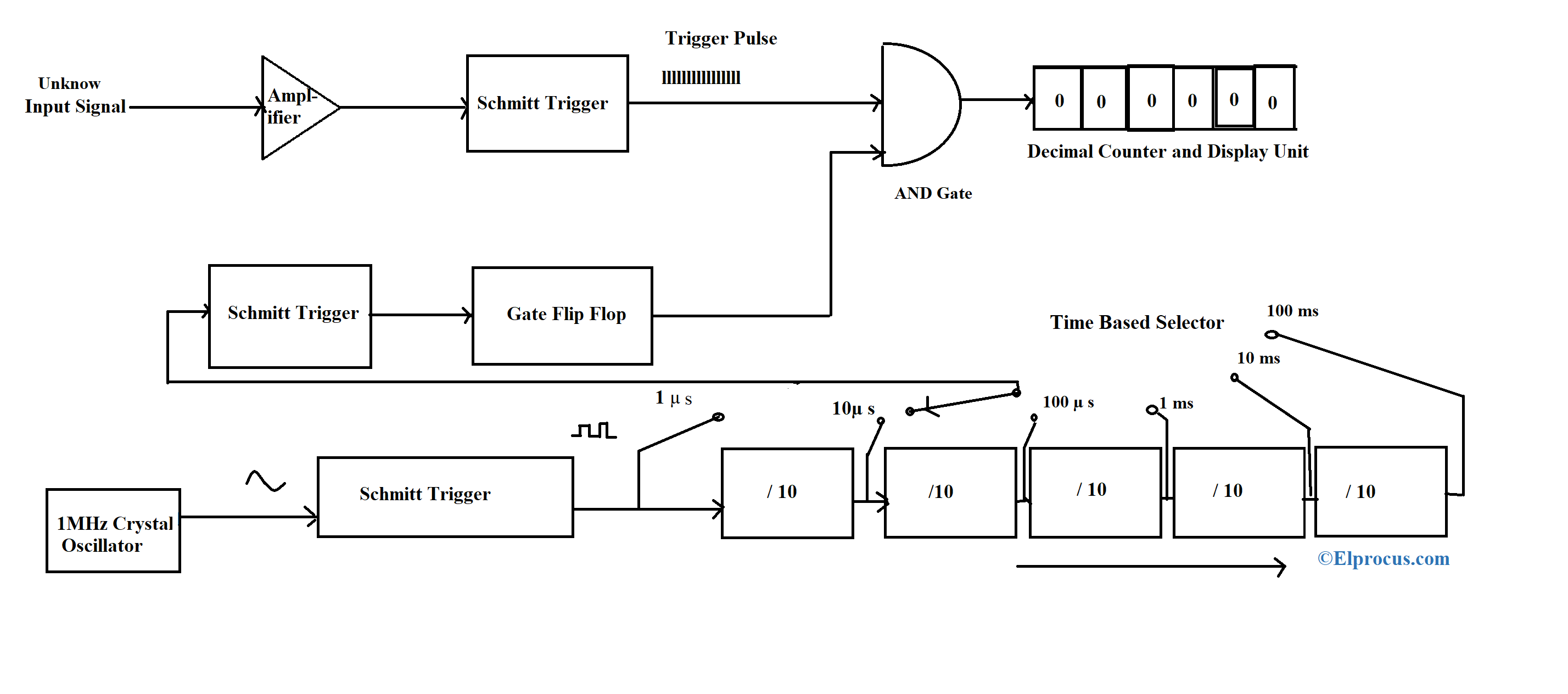
Digital Frequency Meter Construction Working And Its Applications

Deep Directed Evolution Of Solid Binding Peptides For Quantitative Big Data Generation Biorxiv
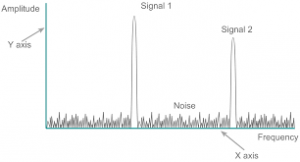
Spectrum Analyzer Working Principle Classfication Its Applications
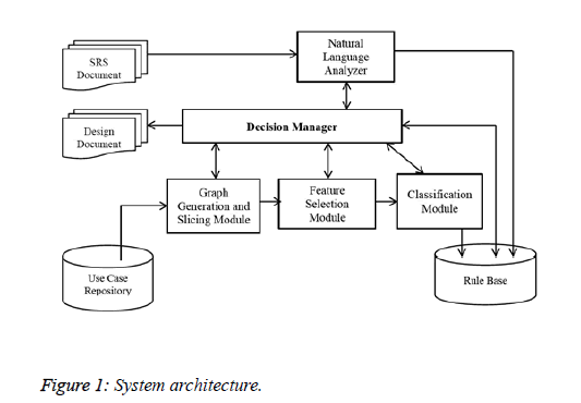
A Software Design Technique For Developing Medical Expert Systems Through Use Case Analysis
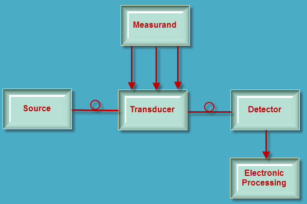
Introduction To Fiber Optic Sensors And Their Types
Show Posts Anders Mikkelsen
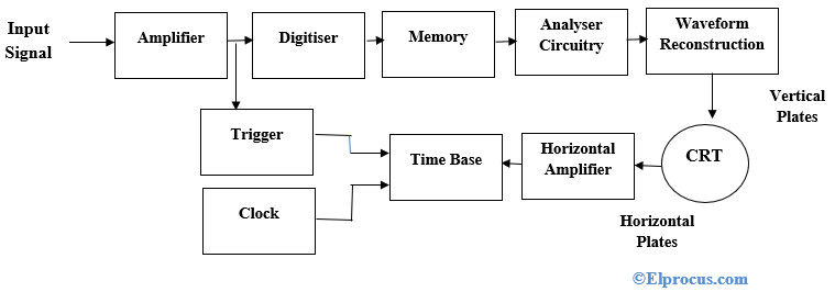
Digital Storage Oscilloscope Block Diagram Working And Its Applications

A181212s31 Jpg
2